
Find the Weak Battery Without Guessing
Charge and rest the pack, then compare accessible batteries under identical conditions. Normal voltage with poor runtime calls for a controlled capacity test.
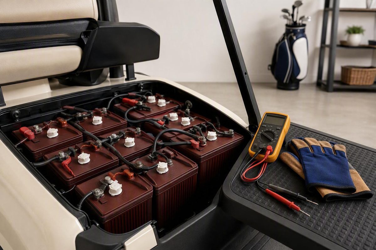
Learning how to test golf cart batteries is not simply a matter of comparing one voltage reading with a chart. Resting voltage can reveal charge imbalance and identify a suspicious outlier, but it cannot prove that a battery retains adequate capacity or can deliver current when the cart accelerates or climbs a hill.
A reliable diagnosis follows a sequence:
- Identify the battery chemistry and pack configuration.
- Stop if inspection reveals a physical hazard.
- Check terminals, cables, and connections.
- Fully charge the pack and let it rest.
- Measure every accessible battery under the same conditions.
- Measure the complete pack.
- Use a chemistry-appropriate load, hydrometer, BMS, or capacity test when voltage alone is inconclusive.
That process helps distinguish a weak battery from incomplete charging, a poor connection, a damaged cable, or a fault elsewhere in the cart.
Know What You Are Testing Before Touching the Pack
Start with the labels. Do not identify battery chemistry from case color, shape, or appearance alone.
Look for the battery model, nominal voltage, chemistry, capacity rating, safety markings, and service instructions. The label or manual may use terms such as:
-
Flooded lead-acid, wet cell, or FLA
-
Gel
- Sealed lead-acid, SLA, or VRLA
- Lithium-ion or LiFePO4
- A named lithium chemistry or manufacturer-specific system
A serviceable flooded lead-acid battery normally has manufacturer-provided access to its individual cells. AGM, gel, and other sealed lead-acid batteries do not provide an owner-serviceable electrolyte path. A lithium battery may include an integrated battery management system, or BMS, but available data and controls vary by model.
Record the following before testing:
- Battery manufacturer and model
- Chemistry
- Nominal voltage of each battery
- Number of separately accessible batteries
- Stated pack voltage
- Capacity rating, if shown
- Charger model
- Applicable battery and cart instructions
The pack voltage depends on how batteries are connected. For example:
- Six nominal 6 V batteries connected in series equal a nominal 36 V pack.
- Six nominal 8 V batteries connected in series equal a nominal 48 V pack.
- Four nominal 12 V batteries connected in series equal a nominal 48 V pack.
These are arithmetic examples, not an exhaustive list of golf-cart configurations. A lithium cart may use one integrated pack rather than several conventional batteries, and other series arrangements are possible.
Keep the measurement levels separate. A benchmark for an individual 8 V battery cannot be applied to a complete 48 V pack. Conversely, a total pack reading cannot identify which of six batteries is weak. You must measure each separately accessible battery to locate an outlier.
Choose the follow-up path by chemistry:
- Every system: visual inspection, connection checks, and multimeter screening
- Serviceable flooded lead-acid: multimeter testing plus electrolyte-level and hydrometer checks when appropriate
- AGM, gel, or other sealed lead-acid: external electrical tests only; do not open the battery
- Lithium: multimeter screening plus compatible BMS diagnostics, controlled load testing, or capacity testing as supported
Use a worksheet rather than relying on memory. The following is an adaptable example; add or remove rows to match the number of separately accessible batteries in your cart.
| Battery position | Nominal voltage | Resting voltage | Loaded voltage | Specific gravity | Temperature | BMS alerts | Inspection notes |
|---|---|---|---|---|---|---|---|
| 1 — pack negative end | |||||||
| 2 | |||||||
| 3 | |||||||
| 4 | |||||||
| 5, if present | |||||||
| 6, if present — pack positive end | |||||||
| Complete pack | N/A |
Label the battery positions physically or draw the pack layout. “Battery 3” is useful only if you can identify the same unit during a later retest.
Do not open an integrated lithium pack or expose internal cells or modules merely to complete the worksheet. Record only owner-accessible measurements and supported BMS information.
Safety Setup and the Inspection That Comes First
A tool, probe, cable end, or item of jewelry must not bridge two terminals. Published battery-testing guidance recommends eye and hand protection, insulated tools, ventilation, charger disconnection, and inspection for case damage, leakage, unusual odor, and abnormal heat before testing (Copow’s battery-testing safety guidance).
Gather the appropriate equipment:
- Digital multimeter with intact, suitably rated leads
- Safety glasses
- Protective gloves appropriate for the battery chemistry
- Insulated tools
- Recording sheet or device
- Flashlight, preferably nonmetallic where practical
- Hydrometer only for serviceable flooded lead-acid batteries
- Battery load tester only when approved for the exact battery type and rating
Before opening the battery compartment:
- Park on a level surface.
- Turn the key off and remove it where applicable.
- Engage the parking brake.
- Disconnect the charger from the cart and its power source.
- Remove rings, watches, necklaces, and other conductive jewelry.
- Ventilate the work area.
- Follow the cart manual for the correct tow/run switch or service-disconnect position.
Shutdown procedures vary by cart. The cart and battery manuals therefore take precedence over generic instructions.
Keep probe tips controlled and expose only as much metal as necessary for contact. Do not place loose tools on top of batteries, and do not disturb high-current connections unless the applicable shutdown procedure specifically requires it.
Inspect every battery before making an electrical measurement. Look for:
- Cracks or impact damage
- Bulging or swelling
- Leakage or unexplained moisture
- Discoloration or melted areas
- Abnormal heat
- Unusual odor
- Damaged, recessed, or loose terminals
Stop owner-level testing if a case is cracked, leaking, swollen, abnormally hot, or producing an unusual odor. Do not connect a load tester or open a cell to investigate further. Follow the manufacturer’s handling instructions and contact the battery manufacturer, cart dealer, or a qualified battery technician.
Inspect the electrical connections as carefully as the cases:
- Heavy or widespread corrosion
- Loose terminal hardware
- Frayed cable strands
- Split or heat-damaged insulation
- Deformed cable lugs
- Dirty contact surfaces
- Incorrectly routed or strained cables
Corroded terminals can increase resistance, while loose connections can restrict current and produce unstable readings. Cases, terminals, and cables should therefore be inspected before meter testing (Mentor Golf Carts’ multimeter procedure).
Do not tighten, remove, or clean energized connections casually. Follow the cart and battery manufacturers’ shutdown, cleaning, and torque procedures. Severe corrosion, damaged cables, or uncertainty about safely isolating the pack is a reason to use a technician.
For serviceable flooded lead-acid batteries, inspect electrolyte level only according to the battery maker’s sequence. Do not assume water must be added merely because caps are accessible.
Never remove covers, drill cases, add water, or insert a hydrometer into AGM, gel, sealed lead-acid, or lithium batteries. Excessive heat or a rotten-egg odor is a warning to stop, not an invitation to continue voltage, load, or hydrometer testing.
Prepare the Batteries for Comparable Readings
Testing conditions matter. A partially charged battery can read low without being defective, while a recently charged battery can show temporarily elevated voltage because of surface charge.
Start by fully charging the complete pack with the correct charger. Confirm that the charger is intended for the pack’s voltage and chemistry. Do not substitute lead-acid and lithium charging profiles unless the equipment manufacturer explicitly permits it.
After charging:
- Disconnect the charger.
- Switch off all cart loads.
- Follow the manual’s shutdown or service-switch instructions.
- Let the batteries rest.
- Use the same rest period and environmental conditions for every battery.
- Record the approximate battery or ambient temperature.
Published rest periods vary. One supplied battery-testing procedure uses at least one hour after charging, while another recommends about six to eight hours so surface charge can dissipate (Leoch Lithium’s resting-voltage procedure).
Another commercial procedure specifies a 24-hour idle period before its open-circuit comparison (Golf Cart Tire Supply’s resting-voltage procedure). These vendor-published intervals are not interchangeable manufacturer specifications. Use the exact battery maker’s procedure when available.
Do not compare one battery measured immediately after charging with another measured after an overnight rest. Standardization is more important than selecting whichever interval produces the most favorable reading.
Recent driving can also distort the comparison. If the cart has just returned from use, let the pack rest according to the applicable instructions before treating the readings as open-circuit measurements.
Temperature affects battery behavior and the interpretation of voltage and specific gravity. Laboratory temperature control is unnecessary for an initial screen, but record whether the batteries are cold, warm, or near their normal operating temperature. Use the manufacturer’s temperature correction when precise acceptance limits are required.
For the initial screen, separately accessible batteries may usually remain connected in series. Measure directly across the positive and negative posts of one battery at a time, not across several batteries or the entire string.
A connected screen is not always the final word. A battery manufacturer or technician may require isolation after charging and resting for a more conclusive individual load or capacity test. Do not remove series cables simply to follow a generic procedure. Disturbing high-current connections without the correct shutdown and wiring plan can expose cable ends and create reconnection errors.
If you cannot confidently identify the pack’s terminating terminals, service disconnect, or correct shutdown state, stop at noninvasive measurements and use a qualified technician.
Test Every Battery and the Complete Pack With a Multimeter
A multimeter test is the fastest way to screen every battery for charge imbalance, but good technique is essential.
Set up the meter
Select DC volts, usually marked V⎓, not AC volts, which may be marked V~. If the meter is not autoranging, choose a DC range above the expected measurement. The range must exceed the voltage of the individual battery when testing one unit and the complete pack voltage when testing the pack.
Inspect the meter and leads first. Do not use a meter with cracked insulation, damaged probe tips, or an unsuitable voltage rating.
Measure each battery
Use your diagram or labels and work in a consistent order:
- Place the red probe on the battery’s positive terminal.
- Place the black probe on the same battery’s negative terminal.
- Hold both probes steady on clean metal contact points.
- Wait for the display to stabilize.
- Record the result by physical battery position.
- Remove the probes without allowing either one to touch another terminal.
- Repeat for every separately accessible battery.
Do not scrape an energized terminal with a probe. If corrosion or contamination prevents stable contact, stop and use the approved powered-down cleaning procedure before retesting.
A negative display usually means the probes are reversed. Correct their placement rather than recording the absolute value without checking polarity.
Do not test one “representative” battery and assume the rest are similar. One weak unit can reduce the performance of a complete series string, so every accessible battery needs its own entry on the worksheet.
Measure the complete pack
Identify the pack’s main terminating positive and negative terminals—the two ends of the complete series string connected to the cart. Do not select an arbitrary positive post at one side of the compartment and a convenient negative post nearby.
Place the red probe on the main pack-positive terminal and the black probe on the main pack-negative terminal. Record the stable result.
The measured pack voltage should be approximately consistent with the sum of the individual readings. Treat this as an arithmetic and measurement check, not as an open-circuit cable-resistance test. If the figures differ materially, check:
- Whether the same rest conditions applied to all readings
- Probe placement
- Terminal identification
- Probe contact
- Arithmetic
- Whether a battery was skipped or measured twice
- Whether a load remained active during part of the process
For example, six individual readings around 8.4 V should add to a total near 50.4 V. That arithmetic does not mean every nominal 48 V system must produce exactly that result, and it does not prove adequate capacity.
Use voltage references carefully
Commercial testing guides commonly publish the following approximate references for rested, fully charged flooded lead-acid batteries:
| Individual battery | Approximate full-charge resting voltage |
|---|---|
| Nominal 6 V | About 6.3–6.4 V |
| Nominal 8 V | About 8.4–8.5 V |
| Nominal 12 V | About 12.6–12.7 V |
These ranges are vendor-published orientation values rather than universal pass/fail limits. Battery construction, chemistry, charge procedure, temperature, rest time, age, and manufacturer specifications all affect interpretation (Vdiagtool’s voltage examples).
Do not apply these lead-acid figures to lithium batteries. Do not compare an individual 6 V, 8 V, or 12 V battery directly with a 36 V or 48 V pack benchmark.
The pattern is often more informative than one isolated number. If five identically rated batteries cluster closely and one remains lower after the same charge and rest, mark the lower unit as an outlier. Verify its terminal contact, inspect its adjacent connections, recharge if appropriate, and repeat the test. One low unloaded reading is not automatic proof that replacement is required.
Interpret Voltage Without Mistaking Charge for Health
Resting voltage mainly indicates present electrical potential. It is useful for screening charge state and comparing batteries, but it does not directly measure remaining amp-hour capacity or prove that a battery can supply current under load.
A battery can reach an apparently normal resting voltage and still deliver poor runtime. Its voltage may collapse when demand increases, or it may reach the discharge cutoff after supplying much less energy than expected. A multimeter screen is therefore the beginning of diagnosis, not the end.
In a series pack, the same operating current passes through each battery. One weak unit can limit acceleration, range, or hill-climbing performance even if the total pack voltage initially appears plausible. Stronger batteries can make the unloaded total look reasonable while concealing the outlier.
Avoid universal difference rules. Commercial guides publish various battery-to-battery spreads, but those figures are not interchangeable across nominal voltage, chemistry, charge state, temperature, and test method. Prioritize repeatable comparison under standardized conditions and use the battery maker’s limits when available.
Three patterns are especially useful.
One battery is persistently lower
If one battery remains lower than its peers after a full charge and standardized rest:
- Confirm probe contact.
- Inspect both terminals and adjacent interconnects.
- Check for corrosion, looseness, or cable damage.
- Repeat the measurement.
- Recharge and repeat under the same conditions if appropriate.
- Escalate to a manufacturer-specified load, hydrometer, or capacity test.
The outlier is a suspect, not yet a conviction.
Every battery reads low
Simultaneous low readings make the charging conditions the first question. Check:
- Did the charger complete its cycle?
- Is it compatible with the pack voltage and chemistry?
- Was charging interrupted?
- Are the charge receptacle and main connections sound?
- Is a load remaining on the pack?
- Were the batteries tested after driving rather than after a full charge?
Incomplete charging, a charger problem, a parasitic load, or a poor pack connection can make every battery appear weak. Do not assume all units failed together until charging has been verified.
Resting readings look normal, but the cart performs poorly
Short range, sluggish acceleration, weak hill climbing, frequent charging, or extended charging time can justify further investigation, but none is battery-specific proof. If resting results look reasonable while performance remains poor, use a controlled load or capacity test.
This distinction is particularly important with LiFePO4. Its comparatively flat discharge curve limits how precisely resting voltage can indicate charge state or health. Compatible BMS information and controlled capacity results are often more informative than a single open-circuit measurement (WattCycle’s discussion of BMS and capacity testing).
Use a Controlled Load or Capacity Test for Stronger Evidence
A load test applies a controlled electrical demand while voltage is recorded before and during the test. It addresses the question that resting voltage cannot answer: what happens when the battery must deliver current?
A battery that drops disproportionately more than comparable batteries under the same specified load may have reduced capacity, elevated internal resistance, or a failing cell. The result must still be interpreted in context.
There is no responsible universal loaded-voltage or voltage-drop cutoff for every golf-cart battery. The correct test depends on:
- Battery chemistry
- Nominal voltage
- Capacity and rating
- Charge state
- Load current
- Load duration
- Battery temperature
- Tester design
- Manufacturer pass/fail specifications
A threshold intended for one 12 V battery cannot automatically be applied to a 6 V or 8 V battery, a complete pack, or a lithium system.
At a high level, the controlled workflow is:
- Fully charge the battery using the correct procedure.
- Let it rest as specified.
- Inspect the battery, terminals, cables, and tester.
- Connect a suitably rated tester exactly as its manufacturer directs.
- Record the starting voltage.
- Apply the specified load for the specified duration.
- Record voltage while the load is applied.
- Stop at the required time.
- Allow the battery to recover.
- Compare the result with the battery and tester manufacturers’ criteria and with peer batteries tested identically.
Do not extend the test because the result “looks close,” and do not repeat a high-current test without the required recovery period. Stop if the battery, terminal, cable, or tester becomes abnormal.
Avoid improvised substitutes such as lifting driven wheels and pressing the accelerator, holding the cart against the brake, or driving uphill while someone handles meter probes. These methods do not provide a controlled load and introduce movement and high-current connection risks. Use suitable equipment or obtain professional testing.
Professional load testing is preferable when:
- You are unfamiliar with the tester.
- Cables or terminals are damaged.
- Readings are unstable.
- High-current connections must be disturbed.
- The battery model’s test specification is unavailable.
- The pack cannot be safely isolated.
- A lithium system reports an undocumented protection event.
- Results conflict or cannot be reproduced.
A controlled capacity test is the stronger tie-breaker when resting voltage appears acceptable but real-world runtime remains poor. In principle, the battery is fully charged and discharged through suitable equipment to the manufacturer-defined cutoff while delivered capacity is measured. The result is then compared with the battery’s rated or manufacturer-specified expected capacity.
Capacity testing requires the correct current, cutoff, temperature conditions, and equipment. Commercial guidance likewise distinguishes open-circuit voltage from controlled discharge testing as a measure of usable capacity.
If the required equipment, cutoff, load profile, or manufacturer specifications are unavailable, use a qualified battery service rather than inventing a test.
Choose the Follow-Up Test for the Battery Chemistry
Multimeter screening applies broadly, but the next diagnostic step depends on what is inside the case.
Flooded lead-acid: hydrometer testing
A hydrometer measures the specific gravity of liquid electrolyte. Use it only on serviceable flooded lead-acid batteries with manufacturer-provided access to the cells.
Wear eye protection and acid-appropriate gloves. Follow both the battery and hydrometer manufacturers’ procedures. A typical process is:
- Fully charge and rest the battery as directed.
- Confirm that the battery is safe to test.
- Open only the approved cell caps.
- Draw electrolyte into the hydrometer as instructed.
- Hold the hydrometer vertically at eye level.
- Record the reading for that cell.
- Return the electrolyte to the same cell.
- Repeat for every cell.
- Apply the specified temperature consideration or correction.
- Secure the caps after testing.
A commonly cited full-charge reference is approximately 1.265–1.280, but that range is not a universal failure standard. Temperature, battery construction, charge procedure, electrolyte condition, and manufacturer specifications affect interpretation. A persistent low-cell outlier or substantial cell-to-cell variation warrants investigation rather than an automatic verdict (Copow’s hydrometer procedure and reference range).
Do not perform a hydrometer test immediately after adding distilled water. The water and electrolyte need time or a charging cycle to mix according to the battery maker’s filling sequence. Testing a newly diluted upper layer can produce a misleading result.
Sealed lead-acid: keep the case closed
Do not open, refill, drill, or hydrometer-test:
- AGM batteries
- Gel batteries
- Other sealed lead-acid batteries
- Batteries marked nonspillable or maintenance-free when their instructions prohibit opening
Use resting voltage, manufacturer-approved load testing, and controlled capacity testing instead.
Lithium: use supported BMS information
A compatible lithium battery may expose diagnostic information through an app, display, communication port, or service tool. Depending on the model, useful information may include:
- Total pack voltage
- Individual cell or cell-group voltages
-
Battery temperature
-
Protection status
-
High- or low-temperature warnings
- Cell-imbalance alerts
- Cycle history
- Capacity or state-of-health trends
Availability does not guarantee correct interpretation. Alert names, thresholds, histories, and reset procedures vary by manufacturer. Consult the exact manual rather than assuming that one battery’s app values apply to another model.
Do not treat a BMS reset as the universal cure for a protection event. A trip may reflect temperature, excessive current, low voltage, cell imbalance, wiring trouble, or another condition.
Escalate recurring protection trips, swelling, abnormal heat, unresolved cell imbalance, damaged wiring, or undocumented alerts to the battery manufacturer or a qualified technician. Do not open a lithium pack to inspect or rebalance internal cells at owner level.
Turn the Results Into the Right Next Step
Good troubleshooting converts observations into the next controlled action. It does not jump directly from “the cart feels slow” to “replace the batteries.”
| Finding | Issue to investigate | Next action |
|---|---|---|
| Meter reading jumps or disappears | Poor probe contact, contaminated terminal, damaged lead, or loose connection | Stop, power down correctly, inspect the contact surfaces and meter leads, then retest |
| One battery remains lower than its peers | Incomplete charge, bad connection, cable problem, or internal battery weakness | Inspect connections, recharge if appropriate, standardize the rest period, and repeat |
| Every battery reads low | Incomplete charging, incompatible or faulty charger, remaining load, or pack connection problem | Verify charging completion, charger compatibility, receptacle, and pack connections |
| Pack voltage differs materially from the sum of individual readings | Wrong terminal selection, poor contact, timing difference, arithmetic error, active load, or skipped battery | Repeat the measurements under identical unloaded conditions |
| Resting voltage appears acceptable, but one unit drops sharply under the same specified load | Capacity loss, elevated resistance, or a cell problem | Confirm with the model-specific load procedure or a capacity test |
| Resting voltage appears acceptable, but runtime is short | Reduced usable capacity, parasitic load, charger issue, or cart fault | Perform controlled capacity testing and check for other loads or electrical faults |
| Flooded battery has one persistent low specific-gravity cell | Undercharge, cell imbalance, or internal deterioration | Verify charge, temperature correction, and manufacturer criteria; seek further testing |
| Lithium BMS repeatedly reports temperature, current, or imbalance protection | Operating condition, wiring issue, cell imbalance, or internal fault | Follow the manufacturer’s alert procedure and escalate unresolved events |
| Batteries and connections pass appropriate tests, but the cart remains weak | Charger, solenoid, controller, motor, wiring, or mechanical fault | Continue systematic cart diagnosis instead of replacing batteries |
Symptoms provide context. Short range, sluggish acceleration, weak hill climbing, frequent charging, and extended charging time justify testing, but they can also result from:
- Corroded terminals
- Loose interconnects
- Damaged cables
- Charger faults
- Parasitic loads
- High-resistance wiring under load
- Solenoid or controller problems
- Motor or mechanical issues
Recharge and retest under standardized conditions before condemning a battery from one unloaded measurement. Look for repeatability: does the same battery remain the outlier after charging, resting, checking its connections, and repeating the test?
A sound replacement decision considers:
- Cracks, swelling, leakage, or other physical damage
- Repeatable battery-to-battery differences
- Manufacturer-specified loaded performance
- Delivered capacity
- Battery age and service history
- Pack balance and matched condition
- Charger compatibility
- Manufacturer replacement guidance
Do not casually install one new battery into a substantially aged series pack. Whether to replace one battery or a complete matched set depends on pack age, condition, test results, and the manufacturer’s matching policy. One weak reading does not mean the entire pack must always be replaced, but individual replacement is not automatically appropriate either.
When the batteries, interconnects, and charging state test appropriately, stop replacing batteries by guesswork. Move to the charger, solenoid, controller, motor, and wiring. For a cart that clicks, fails to move, or has an unresolved control-circuit symptom after battery condition and pack charge have been checked, continue with I Want Golf’s golf-cart solenoid diagnostic.
Hand the work to a professional if you encounter:
- A cracked, leaking, swollen, unusually hot, or foul-smelling battery
- Severe corrosion
- Damaged high-current cables
- Unknown lithium BMS alerts
- An inability to identify the pack terminals
- Inconclusive or unstable load-test results
- A need to disturb unsupported high-current connections
- Missing battery-specific load or capacity specifications
Frequently Asked Questions
Should I disconnect golf cart batteries before testing each one?
Not necessarily for the initial voltage screen. You can usually leave series-connected batteries in place and measure directly across the positive and negative terminals of each separately accessible battery. This lets you compare every unit without disturbing high-current cables.
Isolation may be required for a conclusive individual load or capacity test or when the battery manufacturer specifies it. Disconnect series cables only with the correct shutdown procedure and a clear wiring plan. If you cannot safely identify the pack terminals and service-disconnect process, limit the work to noninvasive measurements and use a qualified technician.
What voltage should fully charged 6 V, 8 V, and 12 V lead-acid golf cart batteries show?
Common approximate resting references for fully charged flooded lead-acid batteries are:
- 6 V battery: about 6.3–6.4 V
- 8 V battery: about 8.4–8.5 V
- 12 V battery: about 12.6–12.7 V
These are vendor-published orientation ranges, not universal replacement limits. Use the battery manufacturer’s specification when available. The figures do not prove adequate capacity and must not be applied directly to a complete 36 V or 48 V pack.
Can a golf cart battery have good voltage but still be bad?
Yes. A battery can show apparently normal resting voltage but have inadequate usable capacity or excessive voltage drop when current is demanded. This can produce short range, weak acceleration, or poor hill climbing despite an acceptable open-circuit reading.
Use a manufacturer-specified load test to observe voltage under controlled demand. If loaded voltage appears reasonable but runtime remains poor, a controlled capacity test provides stronger evidence.
Can I use a hydrometer on AGM, gel, or lithium golf cart batteries?
No. Hydrometer testing is only for serviceable flooded lead-acid batteries with accessible liquid electrolyte. AGM, gel, other sealed lead-acid, and lithium batteries must not be opened, refilled, or hydrometer-tested.
Use external voltage and approved load or capacity tests for sealed batteries. For compatible lithium systems, use supported BMS information such as total voltage, cell or cell-group voltage, temperature, protection status, and alert history.
Should I replace one weak battery or the entire golf cart battery pack?
It depends on the test evidence, pack age, condition of the other batteries, and manufacturer guidance. Do not replace the entire pack solely because of one low unloaded reading. First verify the connection, fully charge and rest the pack, repeat the comparison, and confirm the suspect battery with an appropriate load, hydrometer, or capacity test.
At the same time, avoid casually mixing one new battery with substantially aged series-connected units. If the remaining batteries are similarly aged or have reduced capacity, replacing a matched set may be more appropriate. Consult the battery manufacturer or a qualified technician before choosing between individual and full-pack replacement.
Make the Decision From Repeatable Evidence
Use a conservative sequence: stop for physical hazards; otherwise inspect and correct connections, fully charge and rest the pack, record every individual voltage and the whole-pack voltage, and then use the chemistry-appropriate load, hydrometer, BMS, or capacity test.
Repeatable evidence under a specified load or during a controlled capacity test—not one resting-voltage number—should drive replacement. If the batteries and connections pass, continue to the charger, solenoid, controller, motor, wiring, or mechanical system rather than replacing batteries by guesswork.