
Choose the Right Golf Cart Battery Switch Safely
Learn which golf cart battery switch you need, then check DC voltage, current, load-switching limits, cable size, storage behavior and wiring.
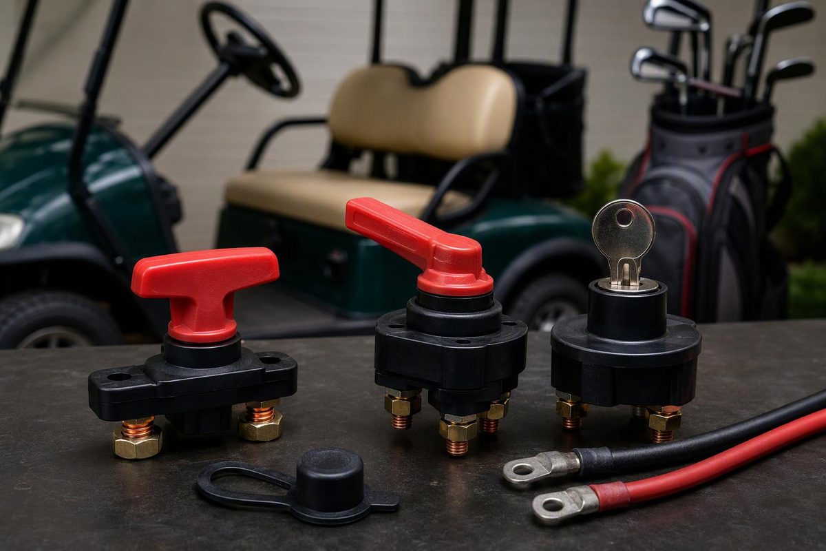
A golf cart battery switch is not one interchangeable part. Use a battery disconnect for pack isolation, the factory tow/run switch for controller modes and a key switch for the enable circuit. A lithium power button may control the battery-management system (BMS) rather than physically isolate the pack. Before buying a disconnect, verify the cart, battery, maximum system voltage and current requirements.
Choose the function you need; the selector shows which switch applies and what must be verified.
Battery Switch Selector
Match the switch to its job before comparing products.
Use a DC-rated master battery disconnect
A disconnect fits this job, but the maximum system voltage and required current ratings are still unknown.
Find those values in the battery, controller and switch documentation before selecting a model.
| Needed Function | Correct Control | Main Check |
|---|---|---|
| Pack isolation | Battery disconnect | DC voltage, current, switching limit and cables |
| Tow or maintenance mode | Factory tow/run switch | Cart manual and braking behavior |
| Driver enable | Key switch | Correct enable circuit and cart model |
| Lithium sleep or storage | Battery/BMS control | Exact battery and charger instructions |
Source: E-Z-GO guidance and manufacturer specifications cited in the article. Final ratings must come from the exact cart, battery and switch documentation.
A 12V gas cart, 36V lead-acid cart and 51.2V lithium conversion do not have interchangeable switch requirements. Identify the make, model, year, powertrain and installed battery pack before ordering a switch.
| Switch | What It Does |
|---|---|
| Battery disconnect or cutoff | Opens the pack cable where the switch is installed. |
| Tow/run switch | Changes the controller’s operating state; it may not disconnect the battery. |
| Key switch | Normally carries an enable circuit, not traction-motor current. |
| Lithium power button or cutoff | May command the BMS or an internal contactor instead of providing visible mechanical isolation. |
A Master Disconnect Provides Isolation, Not a Universal Storage Mode
A master disconnect can provide a clear service-isolation point, reduce drain from cart-side accessories and simplify shutdown. It does not repair a weak pack, stop the battery’s own self-discharge or replace the specified storage procedure for the cart and battery.
For example, the E-Z-GO TXT Fleet guide for electric carts beginning with model year 2014 says its tow/maintenance/storage switch deactivates the controller and electronic braking. It directs owners to select that mode before battery or wiring work and warns that the cart can roll more freely because its anti-roll-back and walk-away features no longer operate. The tow/run switch is therefore not simply an ON/OFF battery knob (E-Z-GO TXT owner’s guide).
Storage instructions also differ by battery and charging system. A Club Car fleet bulletin revised in 2014 describes one method that leaves compatible flooded-battery carts plugged in and monitored. Its alternative disconnects the batteries when continuous charging, AC power or electrolyte maintenance is unavailable. That is an example for the fleet equipment covered by the bulletin, not a storage procedure for every Club Car (Club Car long-term storage bulletin).
Lithium instructions vary as well. Allied tells owners of its Drop-in-Ready system to use the battery cutoff when storing a cart for more than a week. Trojan says its lithium BMS continues to consume some power in storage mode and recommends checking state of charge periodically (Allied best-practices guide; Trojan lithium storage guidance).
Use the current manuals for both the cart and its installed battery. Turning a switch off and leaving the cart for winter is not a universal storage plan.
Match the Disconnect to Maximum DC Voltage
A disconnect’s maximum DC voltage must cover the highest voltage it can experience in the installed system. That value can be higher than the cart’s 36V or 48V label, particularly with a 51.2V nominal lithium pack.
Confirm the battery’s maximum charge voltage and the switch manufacturer’s application limits. Do not assume that a switch marked “48V” suits every nominally 48V cart when the rating leaves little or no margin.
A high current rating cannot compensate for inadequate voltage capacity. One Blue Sea heavy-duty switch, for example, is rated for 500A continuously but only 32V DC. Its voltage limit rules it out for 36V and 48V packs despite the substantial current rating (Blue Sea HD-Series specifications).
Continuous and Short-Duration Current Ratings Both Matter
Check the controller’s battery-current limit, specifications for any motor or controller upgrades, and the battery BMS’s continuous and peak-discharge limits. The disconnect needs:
- a continuous-current rating adequate for the sustained load;
- an intermittent rating adequate for the duration of acceleration and hill loads;
- terminals and approved cable sizes that support the published ratings; and
- a DC rating rather than an AC-only rating.
There is no dependable universal rule that 300A is enough. Larger tires, rear seats, lift kits, and motor or controller changes can alter sustained and peak demand.
Manufacturer tables also show why the complete datasheet matters. Littelfuse lists manual disconnects from 40A to 600A continuous, with options for 12V, 24V and 48V DC systems. The actuator’s appearance does not establish its electrical capacity (Littelfuse manual disconnect overview).
Carrying Current Does Not Mean a Switch Can Interrupt It
A disconnect can carry substantial current while closed yet have a much lower safe switching-current rating. The cited Blue Sea switch carries a 500A continuous rating but lists a 25A switching rating.
Unless the manufacturer explicitly permits switching at the cart’s operating current, stop the cart, release the accelerator, turn the key off and allow the controller to power down before operating the disconnect. Treat it as an isolation switch, not an emergency brake or a substitute for the cart’s normal control circuit.
The New Switch Must Preserve the Cable System
A disconnect adds terminals and usually more cable to a high-current circuit. Match the existing cable gauge and suitable terminal materials, use properly crimped lugs, cover exposed studs and follow the switch manufacturer’s torque specification. Route cables away from sharp edges, moving parts and flooded-battery caps.
Do not reduce cable size merely because a switch accepts a smaller lug. Blue Sea’s specification page identifies the cable size and quantity used to achieve its published rating, along with terminal torque and cable-clearance requirements.
For a gas cart, account for starter current and the installation environment around fuel-system components. Verify that the exact switch is approved for that application. A product described only as “marine style” is not thereby established as ignition-protected.
Map Every Connected Circuit Before Installation
Record which devices must be isolated: the controller, charger, DC-DC converter, lights, USB outlets, stereo, state-of-charge meter and any BMS wake circuit. A disconnect installed only in the traction lead can leave accessories energized. Conversely, placing every lead behind it may interfere with an onboard charger or the battery manufacturer’s required wake and storage behavior.
Battery packs can deliver destructive short-circuit current. Flooded lead-acid batteries also introduce corrosive electrolyte and explosive charging gas. In its industrial battery guidance, OSHA calls for precautions against sparks and arcs, keeping jewelry and metal objects away from exposed batteries, and appropriate eye and hand protection (OSHA battery safety guidance). Those hazards remain relevant to golf-cart work, although the cited requirements address workplaces and powered industrial trucks.
If cable routing, circuit protection, BMS behavior, controller pre-charge or charger wiring is uncertain, have a golf-cart technician specify and install the disconnect. After installation, verify charging in the intended switch position, confirm that every intended load shuts down and check the new connections for abnormal voltage drop or heating under a controlled load.
A Disconnect Will Not Diagnose a No-Move Cart
If the cart already will not run, do not add a disconnect as a speculative fix. First test the batteries under consistent conditions, then trace the enable circuit through the key switch, direction selector, pedal switch and solenoid.
A click does not prove that the solenoid’s main contacts can carry current. Use the solenoid diagnosis sequence before replacing parts.
For a lithium conversion, confirm the disconnect with the battery, BMS, charger and controller as one system. The lithium conversion compatibility guide covers the current, charging and accessory-power checks that a switch alone cannot solve.