
Confirm the Fault Before You Swap the Solenoid
A click usually indicates that the coil caused mechanical movement, but it does not prove that the main contacts can carry operating current.
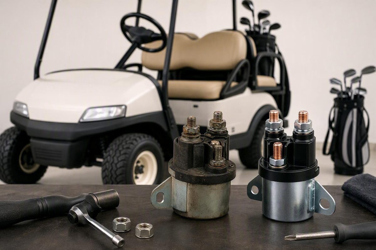
A golf cart solenoid replacement should begin with diagnosis, not a parts order. A click with no movement, intermittent shutdown, rapid chatter, or complete loss of power can also result from weak batteries, damaged cables, switches, interlocks, wiring, a controller, a motor, or a starter circuit.
Before removing anything, identify the exact cart and obtain the applicable service information. Confirm that the solenoid receives the specified control signal, then determine whether its closed contacts conduct properly under load. If replacement is justified, match the complete electrical and physical configuration—not voltage alone—and document every cable, control wire, diode, and resistor connection.
This is a diagnosis and preparation framework, not a substitute for the manufacturer’s wiring diagram, isolation procedure, stored-energy instructions, terminal torque, or test specifications. If those documents are unavailable, stop before disconnecting high-current wiring.
What the solenoid does—and why symptoms alone are not a diagnosis
A solenoid is an electrically operated relay or switch. A relatively low-current control circuit energizes an internal coil, and the resulting magnetic action closes contacts in a higher-current circuit.
In an electric cart, those contacts commonly connect battery-pack power to the motor controller or traction circuit. Although both parts are called solenoids, their duty cycles, ratings, wiring, and operating conditions can differ.
The basic sequence is:
- The driver turns on the cart and selects the required operating direction or start condition.
- Pressing the pedal or issuing the start command closes the applicable switches and interlocks.
- The control circuit applies the specified voltage across the solenoid coil.
- The energized coil pulls the main contacts closed, commonly producing an audible click.
- The closed contacts complete the high-current circuit.
- Removing the command de-energizes the coil and allows the contacts to open.
That sequence creates two separate diagnostic questions:
- Did the coil receive the correct command and move the contact mechanism?
- Did the closed contacts conduct operating current successfully?
A click answers only part of the first question. It does not prove that the contacts are clean, firmly closed, or capable of carrying the required current. Commercial troubleshooting guidance likewise distinguishes coil activation from successful current flow through the main contacts (Nick’s Golf Carts testing guide).
| Symptom | What it may mean | Best next test or action |
|---|---|---|
| No click | Missing control signal, failed coil, poor return or ground, open wiring, failed switch, active interlock, or low supply voltage | Check the battery supply, then measure the model-specified voltage across the coil during the command |
| One click but no movement | Contacts may not be conducting, or the fault may be in the batteries, cables, controller, motor, starter, or downstream wiring | Check supply performance under load and measure engaged voltage drop across the main contacts |
| Rapid chatter | Unstable coil voltage caused by weak batteries, loose connections, or a fluctuating control circuit | Monitor supply and control voltage while the fault occurs |
| Intermittent operation | Loose or corroded connection, damaged cable, intermittent switch, unstable control signal, or worn contacts | Compare control voltage and contact voltage drop during working and failed states |
| Sudden power loss | Failed battery or cable, open connection, control interruption, controller fault, or contact failure | Secure the cart and inspect the complete supply path methodically |
| Burning odor or overheating | A loose or resistive high-current connection, damaged conductor, arcing, or an overheated component | Stop using the cart and follow the manufacturer’s isolation procedure |
| Movement without pedal input | Contacts may be stuck, welded, or receiving an incorrect command | Stop immediately, keep clear, and isolate the cart only through its specified procedure |
| Forward works but reverse does not, or vice versa | Direction control, related wiring, switch contacts, or a direction-specific controller input may be faulty | Inspect the direction-control circuit before condemning a shared solenoid |
Weak batteries and dirty, loose, or damaged cables are deceptive because they may provide enough energy for the coil to click while the high-current circuit remains unable to operate the cart. Key switches, pedal microswitches, direction controls, tow/run or maintenance interlocks, connectors, controllers, motors, and gas-cart starter circuits can produce similar symptoms.
A direction-only problem deserves particular caution. If the cart operates normally in one direction, a shared solenoid may already be performing its function. The direction selector, associated wiring, or direction-specific controller command may be a more productive place to investigate.
Do not continue DIY testing after unintended movement, visible smoke, a burning smell, melted insulation, or scorched terminals. Commercial service guidance treats unintended operation, burning, and scorching as shutdown conditions rather than prompts for continued testing (Canyon Lake Mobile’s solenoid guide).
Confirm the solenoid failure before ordering a part
Start with the supply that makes every other test possible. Check the battery or battery pack using the procedure and specifications appropriate to that battery type.
Inspect the accessible high-current path for:
- Loose cable lugs
- Corrosion or contamination
- Frayed conductors
- Cracked or heat-hardened insulation
- Burned connectors
- Discolored studs or hardware
- Swollen or damaged cables
- Poor cable support that places sideways force on terminals
- Previous repairs, accessories, or undocumented splices
Do not clean or tighten an energized high-current connection. Isolate the cart by the procedure specified for its exact configuration before disturbing the connection.
A useful diagnosis sequence has four stages.
1. Verify the battery supply
Confirm that the battery or pack is charged, connected correctly, and capable of supporting the prescribed test. Include the main cables and battery interconnects in the inspection. If supply voltage collapses when the command is applied, resolve the supply problem before interpreting the solenoid’s behavior.
Because the supplied evidence does not establish a universal lithium isolation or restart sequence, use the battery and cart manufacturers’ instructions rather than applying a generic lead-acid procedure.
2. Observe the solenoid response
Listen for engagement when the correct command is applied and release when the command is removed. Note whether there is:
- Silence
- One decisive click
- Rapid chatter
- Delayed engagement
- Sustained engagement after the command ends
Sound helps determine the next test, but it is not a pass-or-fail test by itself.
3. Check the control circuit
Use the applicable wiring diagram to identify the small coil terminals and determine what voltage should appear across the coil during activation.
If the specified control voltage reaches the coil but the solenoid does not engage, the solenoid becomes a likely fault. Possible internal causes include an open coil, a mechanical problem, or a failed internal connection.
If control voltage is absent, redirect diagnosis toward the key switch, pedal switch, direction control, interlocks, controller outputs, coil return or ground, connectors, and wiring. Commercial multimeter guidance similarly separates control voltage present without engagement from a zero-voltage condition caused elsewhere in the cart (Hartville Golf Carts’ test procedure).
This is live testing. Perform it only if you understand the meter, probe locations, expected readings, circuit behavior, and model-specific activation procedure. Secure the cart against movement and keep people, tools, clothing, and test leads clear of parts that may move or become energized.
4. Assess the engaged main contacts
An engaged voltage-drop test measures the voltage lost across the closed main contacts while the circuit operates under the specified test condition. It asks not merely whether the contacts closed, but how effectively they conduct.
Conceptually:
- Configure the meter for DC voltage in the appropriate range.
- Place the probes across the two main contacts as directed by the applicable procedure.
- Apply the operating command under the specified test condition.
- Read the voltage lost across the engaged contacts.
- Compare the result with the manufacturer’s limit.
Commercial guidance is not entirely consistent. One retailer suggests approximately 0.1 volt or less as healthy and more than 0.5 volt as cause for replacement, while another service business describes less than about 0.2 volt as healthy and approximately 0.4 to 0.5 volt or more as evidence of contact trouble. These are generic commercial troubleshooting ranges, not universal golf cart specifications; the exact service-manual limit takes priority (GOLFCARTSTUFF’s diagnostic discussion).
If a reading is unexpected, stop and verify the procedure before ordering a part.
Voltage drop and resistance are different tests
Do not combine or confuse these procedures:
| Test | Circuit condition | What it evaluates |
|---|---|---|
| Voltage-drop test | Energized and operating under the specified load | Voltage lost across closed contacts |
| Resistance or continuity test | Isolated and de-energized | Continuity or resistance through the disconnected component or test path |
Never select an ohms or continuity range on an energized circuit. Resistance testing belongs on an isolated, de-energized circuit after all relevant power sources have been addressed.
Some commercial guides cite approximately 0 to 0.4 ohm for engaged main contacts, but that figure is not a universal specification. Treat the number only as attributed commercial guidance and use the manufacturer’s test method and limit whenever available (Nick’s Golf Carts’ discussion of contact resistance).
Do not bridge the large terminals or bypass an interlock as a routine DIY test. The supplied commercial and forum material acknowledges sparking or interlock defeat in such procedures but does not provide the manufacturer-level safeguards needed to recommend them.
Decide whether this is a safe DIY repair
Golf cart battery packs and starter circuits present high-current short-circuit, arc, and burn hazards. An incorrect connection or accidental tool contact may also damage electrical components or cause unintended operation. Commercial replacement guidance therefore emphasizes securing the cart, using protective equipment, documenting the wiring, and disconnecting power before removing the solenoid (GOLFCARTSTUFF’s replacement safety guidance).
A suitable basic tool kit includes:
- A digital multimeter rated for the circuit being tested
- Insulated hand tools
- Correctly sized wrenches and sockets
- Appropriate screwdrivers
- Durable wire labels or numbered tape
- A camera or phone
- A wire brush or suitable terminal-cleaning tool
- Eye protection
- Appropriate hand protection
- A manual-approved method of keeping disconnected conductors separated
- The applicable service manual and wiring diagram
Before beginning, record:
- Make
- Model
- Model year
- Serial number
- Gas or electric configuration
- Original or converted battery type
- Nominal system voltage
- Controller make and model, if applicable
- Motor, starter, or starter-generator configuration
- Any lithium conversion, upgraded controller, modified motor, or accessory wiring
- The manual or service information applicable to the serial-number range
Complete this pre-work checklist:
- Park on a firm, level surface.
- Secure the cart against movement.
- Apply the parking brake.
- Remove the key.
- Keep passengers and bystanders clear.
- Select the manufacturer-specified neutral, tow/run, maintenance, or service state.
- Confirm that the correct wiring diagram is available.
- Confirm replacement fitment before disabling the cart.
- Keep jewelry and other conductive objects away from exposed electrical connections.
- Follow the manufacturer’s procedure to isolate the battery pack or starter supply.
- Complete any specified wait, verification, or stored-energy step before removing a high-current cable.
There is no single battery-disconnection sequence or waiting period supported here for every lead-acid cart, lithium cart, gas cart, controller, or conversion. Do not substitute a retailer’s generic sequence for the cart, battery, and controller manufacturers’ instructions.
Live testing is appropriate only for someone who understands how the circuit will behave, how the cart is prevented from moving, where the probes belong, and what reading is expected. If you cannot identify the coil and main terminals from the correct diagram, do not experiment.
Stop work and seek qualified help if you encounter:
- Uncertain or undocumented wiring
- A lithium conversion without complete service information
- A modified controller or motor
- Severe corrosion
- Melted or brittle insulation
- Scorched terminals
- A burning odor
- Contradictory or unexplained readings
- Unexpected arcing
- Unintended movement
- A solenoid that will not release
- Repeated solenoid failure
- Missing isolation or stored-energy instructions
Commercial repair guidance specifically recommends professional service for lithium conversions, uncertain wiring, corroded high-current cables, or symptoms that do not clearly isolate the solenoid. It also identifies burning, scorching, and unintended operation as reasons to stop rather than continue testing.
An informational guide cannot supply missing terminal torque, diode orientation, wiring order, controller-discharge instructions, or battery-management shutdown steps for an unidentified cart. If those details are unavailable, pause the repair.
Choose a replacement that matches more than voltage
A solenoid marked for the same nominal voltage can still be wrong for the cart. Fitment may depend on coil voltage, current capacity, duty cycle, terminal arrangement, mounting footprint, controller configuration, polarity requirements, suppression components, and serial-number range.
Use a fitment worksheet rather than relying on a search-result title:
| Fitment item | What to record |
|---|---|
| Original part number | Every number on the old unit and any documented superseding number |
| Original label | Manufacturer, coil voltage, ratings, duty, and markings |
| Cart identity | Make, model, year, and serial number |
| Power system | Gas or electric, nominal voltage, and battery type |
| Application | Traction contactor, controller supply, starter, or starter-generator circuit |
| Duty type | Continuous or intermittent, as specified |
| Current rating | Continuous and other relevant manufacturer-defined ratings |
| Terminal count | Number and type of main and control terminals |
| Terminal markings | Battery, controller, motor, starter, coil, positive, negative, or other identifiers |
| Mounting | Hole spacing, bracket, footprint, and required orientation |
| Controller | Manufacturer, model, and rating |
| Diode | Presence, part or rating, position, and documented orientation |
| Resistor | Presence, resistance or part number, rating, and connection |
| Wiring notes | Cable side, coil return, polarity, stacked-lug order, and accessories |
Gas-cart starter solenoids serve a different application. Physical resemblance does not establish interchangeability.
Retail inventory illustrates the complexity. One Club Car seller lists products across 12V, 24V, 36V, 48V, and 72V, along with multiple amperages, terminal counts, footprints, controller references, model-year descriptions, resistors, and diodes. That variety demonstrates why voltage alone is insufficient, but the retailer’s fitment and model-year statements still require verification against the cart’s serial number and manufacturer documentation (Golf Cart Tire Supply’s Club Car listings).
Compare three sources before buying:
- The old solenoid’s complete label and physical arrangement
- The applicable service manual or manufacturer parts information
- Fitment data from the manufacturer or a supplier willing to confirm the serial number
Resolve any conflict before ordering. A retailer’s broad “fits” statement is not equivalent to manufacturer confirmation.
A higher advertised amperage or “heavy-duty” label is not automatically an upgrade. The replacement must still have the correct coil voltage, duty cycle, controller compatibility, terminal design, mounting arrangement, and suppression configuration. A physically larger contactor may not mount safely, while a different coil may operate incorrectly in the control circuit.
Preserve battery-side and controller-, motor-, or starter-side identification even when the main studs appear identical. The complete installation may remain orientation-sensitive because of terminal markings, internal construction, cable routing, diode or resistor placement, or model-specific requirements.
Treat external diodes and precharge resistors as circuit components, not optional accessories. Record their markings, position, connections, and orientation, then compare them with the applicable diagram. Do not copy another cart or guess from a generic image.
Locate the solenoid and document every connection
On an electric cart, the solenoid is commonly near the battery pack, controller, or electrical compartment. On a gas cart, a starter solenoid may be near the starter or starter-generator circuit. Exact access and component placement remain model-dependent.
A typical recognition checklist includes:
- Two larger high-current studs or connections
- Two or more smaller control or coil terminals
- A metal or molded body
- Mounting hardware or a bracket
- Heavy cables leading toward the battery, controller, motor circuit, starter, or starter-generator
- A possible external diode or resistor
- Terminal letters, polarity symbols, or circuit markings
Before disconnecting anything, take clear photographs:
- Straight on
- From both sides
- From above
- Close-ups of terminal markings
- Close-ups of stacked cable lugs
- Separate images of any diode and resistor
- A wider view showing cable routing and mounting orientation
Label wires by confirmed function rather than color alone:
- BATT — battery-side high-current cable
- CTRL/MOTOR — controller- or motor-side high-current cable
- STARTER — starter-side cable on an applicable gas configuration
- COIL+ / TRIGGER — positive or switched coil command, only when confirmed
- COIL− / RETURN — coil return or ground, only when confirmed
- DIODE-A / DIODE-B — each diode end, with orientation documented
- RES-A / RES-B — each resistor connection
- AUX-1 / AUX-2 — additional documented control connections
Do not infer polarity from wire color. Prior repairs or conversions may have changed the wiring. Record the terminal marking and, where visible, the conductor’s physical destination.
Draw a simple connection map showing the installed orientation, every terminal marking, each conductor, stacked-lug order, and diode or resistor position. Compare the map with the correct wiring diagram before removal. If they disagree, determine whether the cart was modified or the wrong diagram is being used.
Keep gas and electric layouts separate:
- Electric cart: identify battery-side power, controller or traction-circuit power, coil command, coil return, and any precharge or suppression components.
- Gas cart: identify battery or starter supply, starter or starter-generator side, start-command circuit, return path, and model-specific interlocks.
Transferring wires from memory is risky. A similar-looking replacement may use different terminal positions or accessory arrangements. An incorrect connection can produce a no-power condition, abnormal operation, heating, or component damage.
General golf cart solenoid replacement sequence
The following is a general workflow subordinate to the service manual. It does not prescribe a universal battery order, terminal polarity, diode orientation, cable sequence, torque value, or service-mode setting.
-
Secure and identify the cart. Park on level ground, prevent movement, apply the brake, remove the key, and select the manufacturer-specified service, neutral, direction, or tow/run state. Confirm that the correct manual and fitment-verified replacement are available.
-
Isolate all relevant power. Follow the model-specific procedure for the battery, battery pack, or starter supply. Complete any required controller or lithium-system steps. Verify the prescribed safe state rather than assuming the key switch has isolated the circuit.
-
Audit the existing installation. Review the photographs, labels, and connection map. Inspect the high-current cables, control wires, terminals, mounting area, diode, resistor, and surrounding insulation. If a cable or accessory is heat-damaged, replacing only the solenoid may leave the underlying problem unresolved.
-
Disconnect the wiring as specified. Follow the manual’s required order for control wires and high-current cables. Support each cable instead of twisting its lug against a stud. Keep disconnected conductors separated, identified, and protected using the method specified by the service information.
-
Remove the old solenoid. Support the component while releasing its mounting hardware. Do not pull on wires, twist stiff cables, or force plastic connectors. Reuse hardware only when the replacement instructions permit it.
-
Compare the parts again. Before mounting, compare voltage, application, duty, ratings, markings, terminal count and position, footprint, orientation, diode, resistor, and other accessories. Stop if any material difference lacks documented authorization.
-
Mount and reconnect. Install the replacement in the specified orientation. Return each high-current cable, control wire, diode, and resistor to its documented and manual-confirmed location. Preserve stacked-lug order where required, and use the manufacturer’s terminal torque rather than a generic value or tightening by feel.
-
Perform a pre-power audit. Check for crossed connections, omitted wires, trapped insulation, loose mounting hardware, unsupported cables, conductive debris, damaged boots, and terminals that could contact the frame or another component. Account for every tool, probe, socket, and fastener.
-
Restore power according to the manual. Follow the specified reconnection and service-mode sequence. Stop immediately if there is severe arcing, smoke, unexpected heating, a burning odor, sustained abnormal engagement, or unintended movement.
Do not plan around a fixed completion time. Access, corrosion, seized hardware, brittle connectors, modifications, and damaged cables can materially change the work required.
Test the installation and troubleshoot a cart that still will not run
Begin with a stationary functional check, not an immediate test drive. Keep the cart secured and people clear while following the manufacturer’s post-service procedure.
Look, listen, and smell for:
- Arcing or sparking
- Rapid chatter
- Delayed or sustained engagement
- Smoke
- Heating at a stud or cable
- A burning odor
- Unexpected controller or battery warnings
- Movement without the proper command
Verify that the solenoid responds only to the correct control command and releases when the command ends. A replacement that remains engaged is not ready for service.
Repeat the same control-voltage and engaged voltage-drop tests used before replacement. Using the same model-appropriate method and test condition allows a meaningful before-and-after comparison.
If there is no click
Check:
- Missed or loose coil wires
- Incorrect small-terminal placement
- Absent control voltage
- Coil return or ground
- Key and pedal switches
- Direction control
- Tow/run, neutral, charger, or other interlocks
- Controller command
- Damaged connectors
- Incorrect replacement coil voltage or configuration
If the specified voltage is present across the coil but the new solenoid does not engage, verify the part and wiring before assuming the replacement is defective. If voltage is absent, continue upstream.
If there is one click but no movement
Recheck:
- Battery or pack performance under load
- Battery interconnects
- High-current cable condition
- Terminal placement and tightness
- Voltage drop across the engaged contacts
- Controller power and downstream wiring
- Motor circuit on an electric cart
- Starter or starter-generator circuit on a gas cart
- Any protection device disturbed during the repair
One click still does not establish that the high-current path is complete.
If all power disappeared after installation
Inspect every disturbed connection, including the battery or pack isolation point. Confirm the main supply path, cable placement, coil wiring, interlocks, diode configuration, and connectors moved for access.
An unresolved forum discussion involving a reported 2002 E-Z-GO Shuttle 6 illustrates the uncertainty. After a solenoid replacement, the owner reported losing power; participants redirected attention toward disturbed connections, interlocks, direction-control issues, and test technique. Because no final fault or confirmed repair was documented, the thread should be treated only as an example of post-replacement diagnostic uncertainty—not as a procedure (Cartaholics discussion).
If the solenoid chatters rapidly
Investigate unstable control or supply voltage. Check battery condition, cable connections, coil voltage, return paths, and control-switch stability before replacing the new solenoid. Chatter may occur when voltage rises enough to engage the coil and then falls enough to release it repeatedly.
If only forward or reverse fails
Redirect attention toward the direction switch, direction-specific wiring, controller inputs, and associated connectors. A solenoid shared by both directions is less likely to explain why one direction works normally while the other does not.
Stop testing and obtain qualified diagnosis if the replacement repeatedly fails, will not release, becomes abnormally hot, or is accompanied by melted cables or scorched terminals. Do the same when readings remain unexplained after comparison with the correct diagram and procedure.
Replacement cost and the DIY-versus-technician decision
Separate the price of the solenoid from the cost of diagnosis and completing the repair. A quote may include:
- The solenoid or contactor
- Diagnostic time
- Installation labor
- Replacement high-current cables
- Terminals or protective boots
- A diode or precharge resistor
- Corrosion repair
- Controller or starter-circuit diagnosis
- Mobile-service or travel charges
- Correction of previous modifications
Selected retailer listings and commercial service estimates place solenoid parts at roughly $35 to $180, depending on voltage, duty, current rating, and configuration. One Canyon Lake-area repair business estimates approximately $150 to $275 installed. These are retailer and regional examples—not national averages, guaranteed quotes, or current prices for every cart (Golf Cart Tire Supply listings; Canyon Lake Mobile’s regional estimate).
Some retail pages display two prices beside a product without defining them. Do not describe either amount as a list price, sale price, or discount unless the seller identifies it that way.
DIY replacement is reasonable only when you can:
- Identify the exact cart and circuit
- Obtain the applicable service manual
- Confirm the replacement’s complete fitment
- Isolate the power system using the specified procedure
- Recognize and document every connection
- Use a multimeter correctly
- Distinguish live voltage testing from isolated resistance testing
- Follow the specified torque and reconnection instructions
- Stop when the evidence does not make sense
Use a qualified technician for lithium conversions, modified controllers or motors, uncertain wiring, severe corrosion, damaged high-current cables, burn or heat damage, unexplained readings, unintended movement, or repeat failure.
Before comparing DIY and professional costs, obtain two current figures: a fitment-confirmed part quote tied to the serial number and a local labor quote stating what diagnosis and associated components are included.
Finish with a diagnosis-first checklist:
- Verify the battery supply and high-current cable condition.
- Confirm that the specified control signal reaches the coil.
- Test the closed contacts instead of relying on a click.
- Match the replacement to the exact cart, circuit, and configuration.
- Isolate power using the applicable manufacturer procedure.
- Photograph, label, and map every connection and accessory.
- Reinstall the diode and resistor only as documented.
- Use the specified terminal torque and reconnection sequence.
- Repeat the electrical tests after installation.
- Complete a stationary safety check before driving.
If model documentation is unavailable—or the cart has heat damage, unintended movement, uncertain wiring, lithium modifications, or repeated failure—stop the repair and use a qualified technician.
Frequently asked questions
Does a clicking solenoid mean it is working?
Not necessarily. A click usually indicates that the coil caused mechanical movement, but it does not prove that the main contacts can carry operating current. Check the battery supply, high-current cables, and engaged contact voltage drop using the model-specific procedure. Also consider downstream controller, motor, starter, or wiring faults.
What should I check if the golf cart solenoid does not click?
Check the battery supply and cable connections first. Then use the wiring diagram to determine whether the specified control voltage appears across the small coil terminals during the proper command.
If the correct voltage reaches the coil but the solenoid does not engage, the solenoid is a likely fault. If control voltage is absent, inspect the key switch, pedal switch, direction control, interlocks, controller output, coil return or ground, connectors, and wiring.
Can I replace a 36V golf cart solenoid with a 48V or heavy-duty solenoid?
Not merely because it fits physically. The coil voltage must match the control circuit, while the duty cycle, current rating, controller compatibility, terminals, footprint, polarity requirements, diode, and resistor configuration must also be correct.
A heavy-duty label or higher advertised amperage does not establish compatibility. Confirm the replacement against the old part number, cart serial number, service manual, and manufacturer or verified supplier fitment data.
Why does the new solenoid click but the golf cart still not move?
The replacement may be engaging while another part of the high-current path remains open or unable to carry load. Recheck battery performance, interconnects, cable condition, terminal placement, engaged contact voltage drop, controller or starter power, motor wiring, and every connection disturbed during installation.
Also verify the replacement’s coil voltage, duty, terminal arrangement, and accessory configuration. If only one direction fails, inspect the direction-control circuit rather than assuming the new solenoid is defective.
How much does golf cart solenoid replacement cost?
The sourced retailer and regional service examples are summarized in the cost section above. Actual cost depends on the cart, solenoid specification, location, diagnostic time, labor, cable condition, and whether a diode, resistor, terminal, or other component also requires replacement.
Treat published commercial figures as examples rather than national averages. Obtain a part quote confirmed against the cart’s serial number and a local labor quote before comparing DIY with professional service.